AutoCAD Blocks & Other Assortments: Putting the Pieces Together
In AutoCAD, it can be beneficial to batch objects together into larger objects that can be selected with a single click. Drafters often seek out insertable symbols, representations of repeating geometry, a reference to a previous design or survey, or a way to lock in relationships between parts of a whole. The goal of this blog is to illustrate the advantages, good practices, and conventions for working with AutoCAD blocks and xrefs while giving an overview of the ins and outs of block capabilities, guidelines, and rules in AutoCAD.
Below is a list of several popular objects in AutoCAD that are made up of smaller components.
Polyline
Made of line and arc segments, touching at endpoints. Polylines excel when used to create contours or 2D plans. Lines and arcs can be combined into a polyline with the Join command.

When you select a polyline, grips will appear. Hovering over endpoints provides options including add and remove, which modify the number of vertices. Hovering over midpoints provides options including add, stretch, and convert (this option can switch arcs to lines and vice versa).
Group
Any number of objects can be combined, which serves the purpose of ensuring that the group is only workable as a larger, connected entity. If several commands are going to be run on the same selection set, defining a group can expedite the selection process during those commands. Alternatively, when prompted for selection, a user can typically type previous on the command line to repeat their recent selection set, avoiding the need for a group. In any case, groups are more flexible than polylines because they may include almost any kind of object—not just lines and arcs touching at endpoints.


XREF
an xref (short for external reference) is a link to another .dwg file (that is, another AutoCAD drawing). A coworker’s portion of the project could be brought in as an xref, providing guidance for how elements should be mapped onto other parts of the plan or providing extra detail within a plot.

Block
Any number of AutoCAD objects can be combined to compose a block definition. A block has some similarities to a group—the intention is to combine elements that users may wish to treat as one object. Blocks are favored for re-usable symbols as well as reoccurring design elements like sprinklers or doors. Blocks excel where groups fall short due to their re-usability, flexibility, and the built-in support for their storage. Sometimes, there is a question of whether blocks or xrefs are better tools for the job when it comes to migrating elements from one drawing to another. The goal of this blog is to illustrate the advantages, good practices, and conventions for working with blocks and xrefs while giving an overview of the ins and outs of block capabilities, guidelines, and rules in AutoCAD.
1. The Block Definition
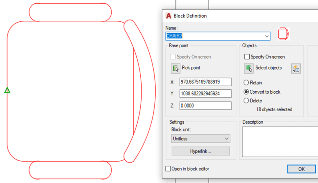
Blocks can be composed of any number of AutoCAD elements of almost any type. For example, a block definition could include lines, polylines, arcs, circles, hatches, and text. Initially, these elements can be drawn anywhere in the model or on the paper space of a layout. After components are drawn, the “block” command transforms the individual objects into a singular whole. The definition includes:

Blocks, once defined this way, initially live specifically in the drawing they are defined in. It would bog down the size of the .dwg if the data for every block were automatically stored in each file. That said, if certain block definitions are used over and over, it may be valuable to store them inside a template—a starting point for future projects. This could prevent users from needing to share the same blocks over and over. We could also create a resource file full of blocks to be shared moving forward.
At this stage, we will focus on the block definition as it has been defined in the current drawing.
2. The Block Reference
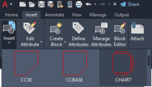
Once a block is defined, the goal is to insert identical instances of it, known as block references. In the Insert tab, there is an insert dropdown that stores all the block definitions within a drawing.

While it is common for some users to use the word “block” as a shorthand when defining or inserting these objects, strictly speaking, the block definition refers to the pieces, grip positions, and settings that make up the combined object, and the block reference refers to a particular instance of the block that has been inserted into the drawing and now has a visible location while drafting and plotting.
3. Block Rules


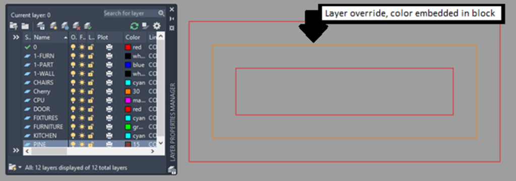
For instance, if the inner finish of a cabinet, represented by a rectangle, were placed on a “Cherry” layer in block editor, then even if the overall cabinet (block reference) is placed on a “Pine” layer in the drawing, the inner finish would still have the properties of “Cherry.”


4. Sharing Blocks Between Drawings: The Old Way


5. The Modern Insert Palette
The Current Drawing tab is the same as looking in the insert tab and picking the block you want from the insert dropdown. While the functionality is redundant here, this palette’s goal is to collect various block tools into one manager.
The Recent tab sees any block definitions created with the “Block” or “Writeblock” command recently, as well as any block references recently inserted. By dragging from the Recent tab, you can share a block definition between drawings and create the first local block reference.
If you right-click any block’s image in the blocks palette, you can choose “Save to Favorites”. This will populate the Favorites tab, thus making a block definition shareable indefinitely.
The Libraries tab can be used in two different ways. One option is to browse to a folder that contains dwg files to insert as blocks (perhaps stored there through previous run-throughs of the writeblock command). The other strategy is to browse to a master drawing that has all the blocks of interest inside it already. Either method should populate the library tab with a collection of shareable blocks.

At the bottom of the insert palette are options such as rotation and angle. Watch out here—if you want to use a preset angle, such as 45 degrees, you type that value next to “Angle.” If you want to set a rotation that potentially varies each time you insert blocks, that’s when you would add the checkmark next to “Rotation.” Note that there are settings for if you want to set an insertion point, a scale, drop instances of the block repeatedly, or drop a version of the block that is exploded into pieces.
The modern palette can be faster and more cohesive than some older methods, but it isn’t always as organized. Newer users may breeze past the finer points of what it means for a block definition to be in the current drawing (local) or inside a different drawing or library folder. I teach AutoCAD students the old, tried-and-true writeblock process before rewarding them with the modern insert palette.
6. Attributes
Attributes are updateable text that lives inside a block definition. Attributes have a tag, a prompt, and a default while working on the block definition.
Tag: The name of an attribute, often beginning with an underscore. The tag is visible if the attribute has not been added to a block or if you are in the block editor. (Remember, BE for block edit.)
Prompt: The text that shows as a block with attributes is inserted, giving the user a sense of what kind of data is requested.
Default: The filler text in case the attribute form is not input when inserted. It may be a number of characters equal to the typical length of the attribute. For instance, “XX” could be the default page number when the total page count is not expected to grow higher than 99 but could easily grow to 10.
Once the block with this attribute is inserted, users can fill in the attributes for that block—at this stage, the filled-in form is called the value of the attribute. This adds a wrinkle where a block definition—which usually would have identical instances everywhere in the drawing—could have different values for page number wherever necessary. With this tool, we could create an attribute that gives each chair a (potentially) unique number or manufacturer. The attributes live inside the block definition and come alive whenever an instance of the block definition with its attributes is inserted as a block reference.
Important Note: Let’s say we run a block edit on a block with an attribute inside it, then create a new attribute or change an existing attribute’s definition. Pre-existing blocks seem to lag behind the new block definition. If the user runs the command “Attsync,” they can select a block reference and then see all block references with that name updated with whichever new attribute default has been installed.
7. Dynamic Blocks
Dynamic blocks are given an automatic way to change form via an extra grip. For instance, users could draft a door that has extra icons for rotating, flipping, or scaling. These dynamic capabilities are defined in the block editor through the block authoring palette and come alive as automatic tools when the block reference is selected in the drawing area. Parameters are the extra buttons given to dynamic blocks. Actions are the powers given to these grips.


Dynamic blocks are helpful when the blocks we plan to place need different orientations, stretch states, scales, or versions. The workflow is streamlined by the presence of these automatic tools.
8. When to Use Blocks
Block definitions can be different in different drawings, thus allowing for flexibility in how they appear in one project versus another. A few examples of how this could be beneficial:
9. When to Use XREFs
Conversely, XFREFs are preferred when a link is desired between an original item and the drawing that will be plotted. A few examples of when this is preferred:
Wrap-Up
AutoCAD has a variety of tools for batching objects together. The best tool depends on which objects are being combined. There can be a bit of art to determining whether the rules, capabilities, and workflows of blocks and xrefs are worth the complexity. Most experienced drafters would agree that assessing these tradeoffs is situation-dependent and sometimes subjective.
My hope is that this blog clarifies some of the finer points of combined objects. For a team of drafters to work together, a good start involves our drawing objects working together harmoniously as well. As Helen Keller once said, “Alone, we can do so little; together, we can do so much.”

