CMI Tools for AutoCAD
Here at CAD Masters we are always trying to find new and unique ways to improve our customer’s experience with AutoCAD. For Civil 3D, we have a set of tools that are available free to our subscription customers and for sale as a standalone product (CMI Tools for Civil 3D). We have recently developed a new set of CMI tools for AutoCAD users. In this article I will introduce CMI Tools for AutoCAD and briefly explain each tool. For more detailed explanations of the tools, you can see our release notes included with the download and installation. Once you install CMI Tools for AutoCAD, you will notice a new tab labeled ACAD-CMI that hosts all the tools available, as shown in Figure 1.

Polyline Tools
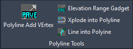
The first set of tools are found in the Polyline Tools panel as shown in Figure 2.
PAVE
The PAVE command to the left, stands for “Polyline Add Vertex.” Alternatively, you could type PAVE in the command line. PAVE allows you to add line or arc segments to either side of an existing polyline. It can also easily remove existing vertices from either side or a polyline. This is particularly useful if you need to continue drawing a model off screen but want to avoid the extra steps of joining a set of polylines together.
ERG
Moving to the right of PAVE, the next tool is called ERG, which stands for “Elevation Range Gadget.” This tool will run a simple elevation analysis on a set of drawing objects such as polylines, circles, or arcs. This can be useful if you are working with contour data and would like to design a surface that conforms easily with the existing surface. This tool will report the minimum, maximum, average, median and the standard deviation of the selected object’s elevation
L2P & X2P
The last two commands are like each other. L2P lets you convert lines to polyline (hence the name) without joining them. It also has the added benefit of flattening the line if it is at different elevations to ensure your polyline is found on the appropriate plane. X2P lets you explode polylines to individual polylines instead of lines and arcs.
File Tools
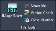
The second set of tools are in the File Tools panel as shown in Figure 3.
IMAGIN
IMAGIN stands for “IMAGe INsert” and this command is a more deliberate way to insert an image into your drawing. It will enable you to insert a regular image as well as a geo-referenced image. You will have options to specify which layer the images may come in at as well.
CLEAN
The CLEAN FILE command is an in-depth tool used to remove clutter from a drawing. It will audit the drawing as well as purge the registered applications, materials, and shapes from the drawing. This will help alleviate ‘slowness’ and decrease the chance of a crash, a great tool for new users.
CIAO
The command labeled CIAO stands for “Close Invoke All Others” and it is a neat little file management tool. In Revit, you have an option to close all other inactive windows. Close all Other, in effect, does the same thing in that it will start to close all other drawings that are opened but not being edited. A great tool for users who tend to have cluttered workspaces.
VCHECK
The last tool, VCHECK, stands for “Version CHECK.” As many users know, there are sometimes compatibility issues between years. It is not always readily available especially when receiving drawings from other drafters. This tool is a quick and easy way to check what version the drawing file has been saved in as well as if there are any AEC objects inside of it
Annotation Tools
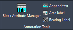
The third set of tools are related to text editing and is hence found in the Annotation Tools panel.
BAM
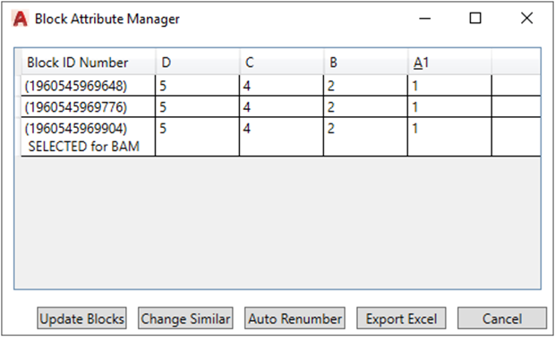
BAM stands for “Block Attribute Module” and is a good tool to use when you need to quickly edit multiple attributes over many blocks. It also enables you to export the attributes to an excel file to report values.
APPEND
APPEND is used to append a note or piece of text at the beginning or the end of existing text. This may seem like a small tool but can be incredibly useful when needing to make a large set of changes.
BEARING
BEARING lets you select a line and insert a piece of text describing the direction of the line by noting the quadrant and angle of that quadrant.
ALIBI
The final tool is called ALIBI which stands for “Area Label Inside Boundary Item.” This tool will label the area of a closed polygon or circle.
Viewport Tools
DVIEW Twist
The panel labeled Dview Twist deals with tools that involve changing or rotating the plan view. The first button, “Set Dview Twist Angle,” lets you twist you twist your plan view by a selection of two points The second button “Set Dview Twist to 0”, Resets the angle to 0 if it has been changed. The third button labeled “Twist Annotation” will orient your selected text to current twist or angle of the plan view.

Crosshair Angle Tools
The fifth panel is labeled Crosshair Angle Tools and is usually used in conjunction with the Dview Twist tools previously described. When you set the new plan view angle with Dview Twist, your crosshairs and orthogonal direction are still going to be about the original plan view.
The first button in this panel lets you set the new crosshair angle the same way you would set the Dview Twist angle. Likewise, the second button called “Crosshair Angle 0” resets the crosshair angle to the original plan view’s orthomode. The last button labeled “Crosshair Angle +” lets you set the crosshair angle horizontal to the current dview twist angle.
Viewport Tools
The final panel is labeled Viewport Tools and is primarily used in your drawing’s layouts and paper space. The first button labeled MTV stands for “Match Through Viewport.” It works just like the command to match properties, except you can use it through a viewport. If your company has certain objects hatches line types etc. saved to a template, you can use this command to directly match those objects through the viewport into paper space. I found this tool to be practical and innovative.
VTWIST stands for “View Twist Checker” and is a shortcut for a standard AutoCAD command. The tool enables you to view the current twist angle so it can noted by the user.
The last two commands PSLT1 and PSLT0 have to do with the drawing variable PSLTSCALE. Each one of these automatically sets the variable to either 1 or 0, respectively. For more information about PSLTSCALE, click here.
Conclusion
There are quite a few useful tools available with this product. These tools will be new favorites for many users based on the number of complex tasks that they simplify! Please let us know in the comments what you would like to see in the next version of CMI Tools for AutoCAD!
Interested? Purchase now for $59 or Contact Us for a Free Trial
