Grading Optimization in Civil 3D 2022
Civil 3D 2022 comes with a powerful new functionality for AEC Collection subscribers, the Grading Optimization tool for Civil 3D. This tool is designed to automatically create grading surfaces with design input. You can find this download in your portal at manage.autodesk.com as a separate installation from Civil 3D. In this article I will attempt to show what the Grading Optimization tool is capable of.
Selecting Topography for Grading Optimization
When using the grading optimization tool, you will need an existing topography to build on and as such, this is the first step to using the tool. Afterwards, with either vanilla AutoCAD or Civil 3D items, draw basic information about the grading. For instance, you could draw the outline of the grading area with a polyline, or you could draw a point or COGO point to denote a low point of your optimization. Figure 1 below displays a simple example.

As you can see above, there is an existing topography I will use to grade towards and then there are some simple AutoCAD objects. There are two rectangles that will denote two different zones with different grading criteria, and then there is a polyline that is bisecting the inner rectangle. This line will be used to denote a drain line. In other words, I will tell it to grade in such a way that has a direction that follows the line.
Converting to Grading Optimization Objects

To convert these objects into Grading Optimization objects, you will first need to bring up two palettes. To do so, navigate to the Analyze Tab > Grading Optimization Panel and select the button for “Grading Objects.” This will pull up the Grading Object Browser and the Tool Palette focused on the Grading Objects tab
In the tool palette, select a type of object you would like to create. Afterwards, select the objects that are going to be comprised of the grading type. In our example we are going to create a drain line from the bisecting polyline and then create two zones from the rectangles. Once you create these objects, you should see them listed somewhere in your Grading Objects Browser.

Setting Grading Criteria
After creating the objects, you can edit the criteria the items are supposed to follow. For instance, Zone-1 is our inner zone and we can set the minimum and maximum to be a customized slope. To edit the grading object, simply select it in modelspace or from the Grading Object Browser.

Launch Grading Optimization Tool
After setting up all the criteria, you can now launch the Grading Optimization tool. Select the Grading button located in the Analyze Tab > Grading Optimization Panel and the tool will then launch as shown in our example below.

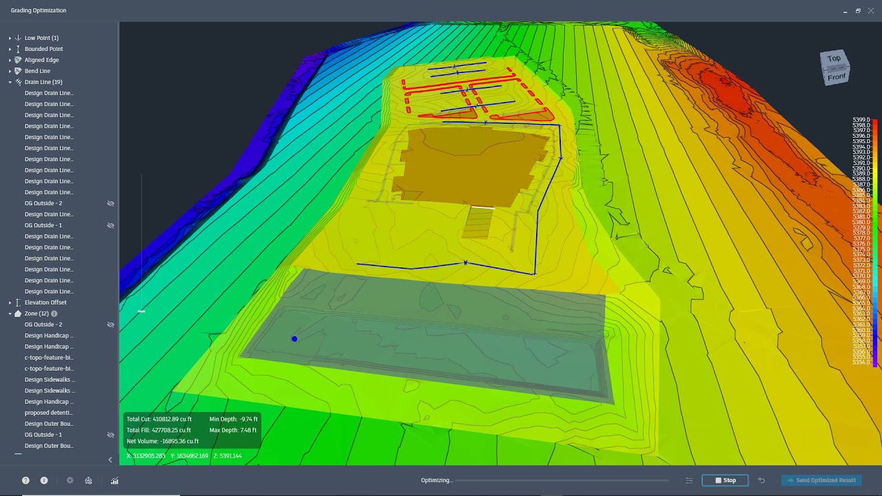
There is plenty to go over but for the purpose of this blog we will keep it simple. In this modelspace you can see the grading objects we created as well as the existing topography. On the left, we can see the Grading Object Browser. This allows you to edit any criteria the objects are set with. We can pan, rotate, or zoom with our mouse to take a close look at our grading area. There is a visualization reference on the right side, right underneath the navigation cube. At the bottom, there are options to change grading preferences and optimization settings. To start the optimization, click the “Optimize” in the bottom section. This function will start to retriangulate and after that, will start the grading process.
Visualization Toolbar
As it is optimizing, the “Optimize” button will turn into a “Stop” button. When you are satisfied with your optimization, you can finish with the Stop button. As it is optimizing, there are different ways to view the process. On the bottom of the interface there is a “Visualization Toolbar” button. Selecting this will turn on the toolbar in modelspace. Again, we won’t go into too much detail so feel free to investigate each of these display options. One display option you can view is the “Violations” the program is able to determine. These violations are essentially triangles that do not fit the criteria specified (i.e. they may not follow the slope criteria in their zone). Below is an example of how that looks.

While the tool runs, the number of violations should hit a minimum amount. If it does not, you can always stop the optimization and reset your criteria from the Grading Object Browser and try again. Otherwise, if you are satisfied with the optimization you can Stop it and send the resulting surface to C3D as its own TIN Surface. To do so, click the button “Send Optimized Result” and the Grading Optimization window will close. In Civil 3D, you should see a new window appear.
Save Grading Optimization Result

From our example we can create a surface and some feature lines. If we had any points (like a Low Point) we could also create a COGO point in our model. To create the surface, ensure that the Surface “switch” is turned on and be sure to select a name and style the surface will take on. Below is our resulting surface.

Note: It does not add an outer boundary but instead combines our existing topography with our grading optimization. You can always add the boundary yourself by editing the surface
The automation of design criteria is a great tool that can be used as a preliminary source to use as a base for your grading design. You can download the Grading Optimization tool from manage.autodesk.com. Let us know if this helps or if you have any comments.

