Civil 3D Grading Cheat Sheet
Whether you’re working on road design, land development, or any other civil engineering project, understanding the ins and outs of grading in Civil 3D is essential. In this tutorial, we’ll provide you with the ins and outs of building a proposed grading surface in Civil 3D. Grading in Civil 3D involves creating proposed surfaces using various elements like points, feature lines, polylines, and gradings, and then comparing them to existing surfaces to determine volume differences. To navigate this complex process, we’ve broken it down into manageable steps and provided tips and tricks to enhance your proficiency.
Let’s dive into the world of Civil 3D grading and unlock the secrets to efficient surface manipulation, volume calculations, and more.
Building a Grading Surface
The objective in grading is to build a proposed surface using points, feature lines, polylines, and gradings. Then you may calculate volumes comparing it to the existing surface.
Right-click “Sites” > New
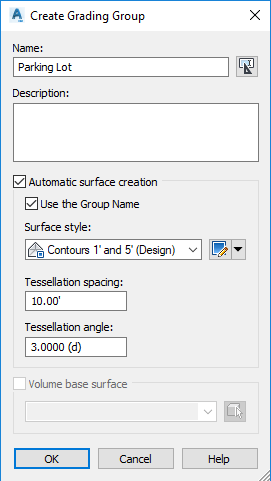
Dig into the site and right-click “Grading Groups” > New
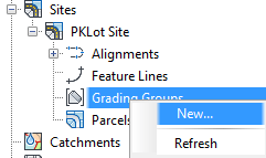
- Checking the “Automatic Surface Creation” box is extremely useful as gradings are automatically added to the surface, but it comes with some risk. Complicated grading projects can cause slowness and possible crashing.
- Now using points, features lines, 2D polylines, 3D polylines, or Gradings, add the necessary data to the surface, under the definition.
Creating and Modifying Grading Entities
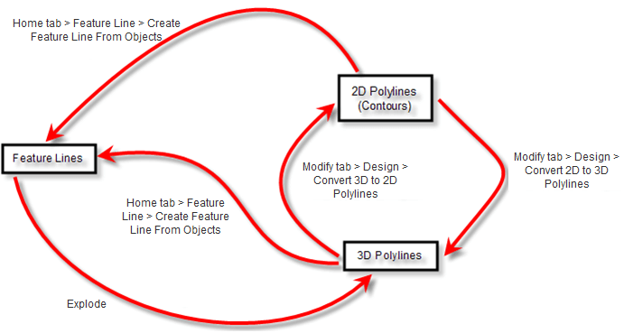
This figure below shows the path one can take to create and modify different entities. There are advantages and disadvantages to each type of entity. By far, the most versatile are feature lines. You may convert these entities by following the arrows below.
Surface Data Workflow for Grading
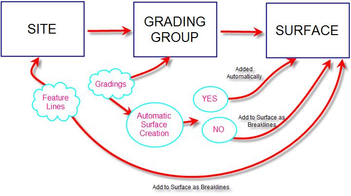
The figure below explains the general workflow when adding data to a surface when using the grading tools.
Feature Lines
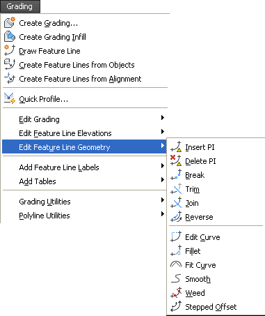
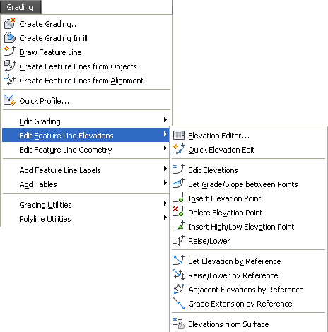
A thorough explanation of feature line commands exists in the Civil 3D Advanced manual, which can be purchased here. You can also gain access to this manual and the rest of the CAD Masters training materials by subscribing to a software product or taking a class with our award-winning training staff. Please refer to that for additional information. The feature line commands can be found in the Grading pulldown or on ribbons.


Points
Select the Point Creation Tools under the Home tab of the ribbon.
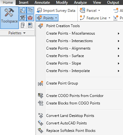

Create Points on a Surface

- Random Points – This command reads the current surface and the user picks an x,y location in the drawing and the command will enter the elevation based on the surface.
- On Grid – This command will prompt for rotation angle, x, and y spacing to place points in the same fashion as the ‘Random Points’ command.
- Along Polyline/Contour – This command places points based on a surface elevation along a polyline. The command prompts for the spacing.
- Polyline/Contour Vertices – This command places a point on each vertices of a polyline, this will not read the surface elevation.
There is also a command to change existing points to the elevation of the surface.
Points > Edit > Elevations from Surface
Create Points based on Slope

- Slope/Grade – Distance – The user picks a starting point, then a second point which denotes direction & distance, then chooses a slope or grade with several intermediate points.
- Slope/Grade – Elevation – The user picks a starting point then a second point which denotes just direction. The user then chooses grade/slope and elevation to end.
- High/Low Point – The user picks a start point then a second point. The user will be prompted from each point the desired grade or slope to find the intersection.
Create Points by Interpolation
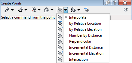
- Interpolate – The user picks two Point objects and enters the number of intermediate points they desire.
- By Relative Location – The user establishes two points then is prompted for a distance to place a point FROM the first point along the line defined by the initial two points.
- By Relative Elevation – The user establishes the two points then is prompted for an elevation between two points and the computer places the point at that elevation along the slope defined by the two points.
- Number By Distance – Same command as ‘interpolate’ except the user has more versatility in choosing the two points (i.e. you are not limited to Point objects).
- Perpendicular – The user picks two points to establish a line, then the user picks any point on the screen and the computer calculates the perpendicular point where it crosses the initial two points defined line then places a point at the correct elevation based on the slope of the initial points.
- Incremental Distance – The user established two points with elevation and then is prompted for the increment to set points.
- Incremental Elevation – The user establishes two points with elevation and then is prompted for the elevation increment to place points along the sloped line.
- Intersection – The user has two points to define the first line then two points to define the second line. The user is prompted for the desired offset to each line and will place a point at that location.
Daylighting
In Civil 3D, there is only one way to daylight to a surface; using Gradings.
Select Grading Creation Tools from the Home tab of the ribbon
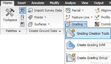
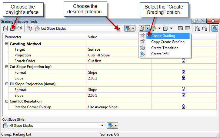
- Select the object to daylight from. This must be a feature line in the same site as the grading group.
- Select the side to search for the daylight surface.
- Apply to entire length? [Yes/No]
<Yes>: This question applies if you wish to add transition slopes along a feature. For example, part of the way I need to slope at 2:1, for another part it needs to be 4:1, and then I need to transition the slope between the regions. - Hitting <enter> out of the command adds the grading object to the surface supplied when you created the surface through creating the grading group (unless automatic surface generation for the grading group is not checked).
Volumes
“Analyze” tab > Volumes Dashboard

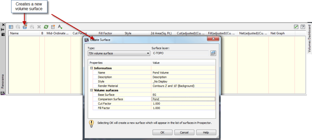
Other Options from the Volumes Dashboard
- Add a boundary to use the bounded volumes option. This will calculate the volumes for a closed area instead of the entire surface.
- Generate Cut/Fill Report – this creates an xml report opened in the default Web Browser.
- Insert Cut/Fill Summary – This creates an AutoCAD entity in the drawing instead of an external report.
“Analyze” tab > Grading Volume Tools
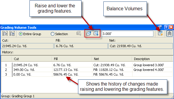
Our Civil 3D Grading Cheat Sheet has equipped you with the knowledge and techniques needed to harness the full potential of Civil 3D’s grading tools.
From creating feature lines to generating cut/fill reports and daylighting surfaces, you’ve gained insight into the diverse capabilities of Civil 3D. Remember that practice makes perfect, and as you apply these techniques to real-world projects, your proficiency will continue to grow.
As we conclude this guide, we encourage you to explore further, experiment, and continue learning. Civil 3D offers a world of possibilities, and your newfound grading expertise is just the beginning of your journey. Keep innovating, keep designing, and keep transforming landscapes with confidence and precision.
If you found this Civil 3D Grading Cheat Sheet helpful, stay tuned for more updates and insights in the world of civil engineering and design. Your success in this field is our ultimate goal.
Happy grading, and may your Civil 3D projects flourish!
© 2022 CAD Masters, Inc. All rights reserved.

