Civil 3D Template Development Part 4 – Styles
In part 3, we started working on our Civil 3D template by addressing Drawing Settings. In this post, we’ll address Styles which some consider styles the beef of the template. How do we get started? We certainly don’t want to create every style from scratch. Reread part 1 – near the end, I discuss options for choosing your starter templates. CAD Masters has pre-built templates that we are happy to share with you. Please inquire.
Firstly, don’t be afraid to create content in your templates for viewing and testing your styles. How else are you going to inspect your work? No matter how dialed in you think a style is, you really will not know until you see it in action. Simply erase all when you are done (and reset your counters – we’ll get to that later). Are you afraid of corruption (of your templates) using this approach? You’re not trying to model the utility infrastructure of Rhode Island! You’re creating simple content to test your styles. Are you worried about not being able to remove styles when you’ve used them? Civil 3D 2012 has a great tool for purging styles.
Style Naming Conventions and Abbreviations
Above - Label will be above the feature in a profile or section view
 Bdr - Border
 Below - Label will be below the feature in a profile or section view
 Bot - Bottom
 Brng - Bearing
 CB - Catch Basin
 Cont - Continuous
 d - Degree
 Dbl - Double
 Desc - Description
 Dir - Direction
 Dist - Distance
Start by creating a list of style naming conventions and abbreviations. This list will provide guidance on naming the styles as you work your way down the list of Civil 3D styles. Here’s a sample of some common types of abbreviations you might need:
Do What You Do and Only What You Do
What kind of civil engineering and survey work do you do? Do not spend time on styles if you do not need them. Don’t even spend time on a style if you’re not sure that you need it. For example, if your last project that used superelevations was four years ago, don’t worry about the Superelevation View Styles, at least for now. You can always supplement your templates later.
ByLayer Styles
Civil 3D objects are similar to AutoCAD blocks with regard to layers. An object has an insertion layer, but it can also have nested, subcomponent layers via the style applied to the object. Further, if the subcomponent layer(s) are set to layer 0, the subcomponent will take on the properties of the insertion layer.
This is a very important concept to understand when setting up styles. For some objects, you may only be interested in the insertion layer. You may want all of the subcomponents to take on the properties of the insertion layer. Accordingly, all of the subcomponents should be placed on layer 0. This is a ByLayer style, and I use them extensively for styles that are not loaded with subcomponents (such as a Profile View Style).
Time to Start Plowing
Without going through every style category, I will try to provide an overview of how to address style creation and editing. Again, hopefully you are starting with pre-built templates. The first step is to, create content and ask yourself questions. Then you will build and edit styles based on the answers. Here’s an example:
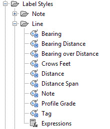
Draw a line and label it with a bearing and distance. Does a bearing and distance label style exist? Is the label on the desired layer? Does the layer have the desired color or plot style? Do you need to label just bearing or distance? If so, create a style for just bearing and another for just distance. Do you want bearing and distance side by side? You get the idea. When you are done, you will hopefully have a nice set of line label styles:


- Line and Curve Label Styles
- Points (very basic styles)
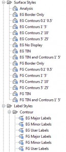
- Surface
- Alignment
- Profile and Profile View
Work on these first. Of course for surveyors, the priorities will be different. And I have a future blog post as part of this series just for surveyors. Stay tuned.
You can next address the following:
- Samples Lines, Sections and Section Views
- Assemblies and Corridors
Corridor object display includes the most complicated styles including Code Set, Link, and Shape Styles. These styles determine how the corridor will look in plan, 3d, and section.
Pipe Networks are another large scale topic that I’ll address in-depth later in this series.
Table Styles
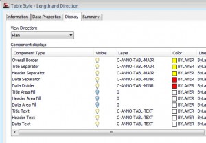
There are over 20 different types of table styles in Civil 3D and they are all very similar. Except for the contents of the table, the style parameters are identical. So make global decisions on the text settings and subcomponent layers for the table styles:

Conclusion
Hopefully, you can use this post as a resource as you tackle Styles in your Civil 3D template. In the next part of this series, we’ll discuss Feature Settings and Command Settings. Styles are great, but only if they are used. Feature Settings allow us to set the default styles when creating objects.


