Coordinate Transformations – Part 2 – Re-Projecting Drawings
Part 1 looked at the coordinate transformation of points in Civil 3D. Continuing on the theme of coordinate systems, now we’ll take a look at performing a coordinate transformation on an entire drawing. This translation is possible in either Map 3D or Civil 3D, and the commands are located in the Map Task Pane. To bring up the Map Task Pane, type MAPWSPACE at the command line, press Enter, and select On. First, we need to make sure the existing drawing is assigned the correct coordinate system.
- Open up the drawing you wish to perform the coordinate transformation on.
- In the Map Explorer tab of the Task Pane, right click on Current Drawing and click Coordinate System.
- Click the Select Coordinate System button.
- Select the appropriate category and coordinate system in that category (the coordinate system in which the drawing currently resides).
- Click OK to close the Select Global Coordinate System window.
- Click OK to close the Assign Global Coordinate System window.
- Save and close the drawing.
Next, a query is used to transform the coordinates of the objects in a new drawing.
- Start a new drawing.
- Assign the coordinate system as described above, this time choosing the destination coordinate system where you want the drawing to end up.
- In the Task Pane, on the Map Explorer tab, right-click on Drawings and click Attach.
- Now we need to create an alias, basically a pointer at the location of the drawings we are working with. Click the Create/Edit Aliases button.
- Enter a name for your Drive Alias, such as the name of your project. No spaces are allowed in the alias name.
- Click the Browse button for the Actual Path, and browse to where the existing drawings are located.
- Click the Add button
- Click Close.
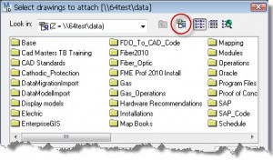
- Select the new Alias we’ve created from the drop-down for Look In, select the existing drawing we want to transform, click Add.
- Click OK to close the Drive Alias Administration window.
- In the Task Pane, on the Map Explorer tab, right-click Current Query, and click Define.
- In the Query Type group, click the Location button.
- For the Boundary Type, make sure All is selected and click OK. You may choose any of the other boundary types, or explore the variety of other query options if you don’t want to bring in the entire drawing.
- In the Query Mode group, select Draw.
- Click Execute Query and let the magic happen.
- Zoom Extents to view the results in the drawing.
- In the Task Pane, on the Map Explorer tab, right-click the drawing that you attached and select Detatch. If you make edits to the drawing entities, there is a possibility that you might edit the original.
We’ve now created a new drawing with the objects in a different coordinate space. Save the drawing, and make sure to distinguish it from the original in the old coordinate space. Note that Map queries do not function on Civil 3D objects, they will be ignored in the query. LandXML export/import is a good way to transform Civil 3D objects.
See also Coordinate Transformations – Part 1 – Translating Point Files Using Civil 3D.


