AutoCAD Civil 3D 2017 New Features
Civil 3D 2017 was just released this April! As always, we recommend waiting until after initial bugs are addressed to install the version, especially if you will be relying on Civil 3D 2017 heavily for business. The summer time is typically when first Service Packs and other updates become available.
Great news comes with this new release of the program. Key additions have been made regarding Data Shortcut Projects and Pressure Networks. The same file type is being used too (AutoCAD Civil 3D 2013 drawing format). However, the Civil 3D 2017 objects are not backwards compatible with the previous version years of Civil 3D.
Since Civil 3D contains all of the features of AutoCAD, it includes those AutoCAD 2017 new features too! See our article presenting the AutoCAD 2017 New Features.
If you want a more in-depth video tutorial, that is available here (the points data referenced is available for download here):
Our favorite Civil 3D 2017 features are listed below:
1. Data Shortcuts Projects –
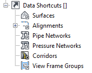
Corridors can now be added to your Project via Data Shortcut. This is an improvement from the previous process of externally referencing the Corridor drawing when it is needed.
Multiple Civil 3D objects can be data referenced into a drawing in one step rather than bringing them in one by one.
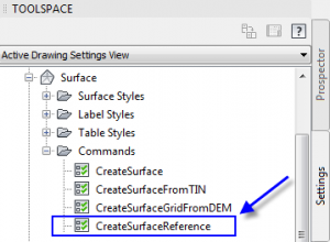
The defining geometry of a reference surface can be brought into the drawing to improve loading of the data reference by editing the CreateSurfaceReference command settings. Though if the source surface definition changes, the new geometry will take some time to load in.
To create data references in your drawings, the Civil 3D objects that are part of your project can be dragged and dropped from the prospector to the drawing area. This is a slightly faster process than right-clicking on the object to reference in.
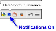
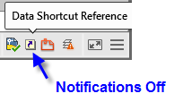
If you find the Synchronizations notifications to be too distracting, then can be toggled on and off using the Synchronize data shortcuts reference button in the Status bar.
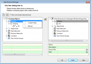
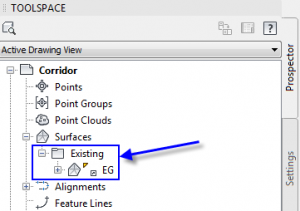
Subfolders can be created to help organize the data shortcuts and data references in both the Data Shortcuts Manager and the main portion of the Prospector. When you create a data reference to a Civil 3D object that is in a sub folder of the Data Shortcuts Project, the sub folder automatically comes in to the main portion of your prospector. (Select image for larger view)
2. Pressure Networks –
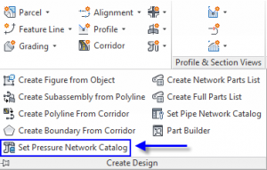
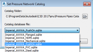
Civil 3D 2017 comes with additional catalogs of parts for creating Pressure Networks. New Catalogs can be loaded in from the Home Ribbon Tab > Create Design Panel drop down. (Select image for larger view)
Table Source: Autodesk Civil 3D 2017 Help
3. Corridors –
When building Corridors with turns, corridor cleanup behavior is now automatically applied for corners made by two tangents (line segments) in the baseline. Unfortunately it does not cleanup corners that use curves. So in those cases where the turns contain curves, feature lines can be extracted from the corridor, adjusted and added targets to clean up the corners manually.
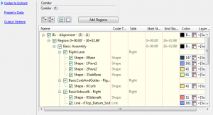
Improvements have been made to the Extract Corridor Solids tool. This tool is available in the contextual ribbon when the corridor is selected. The regions, station ranges, and shapes can be individually chosen. The Property Data tool that first appeared in the Civil 3D 2016 Productivity pack 2 are have been added to the Extract Corridor Solids wizard. (Select image for larger view)
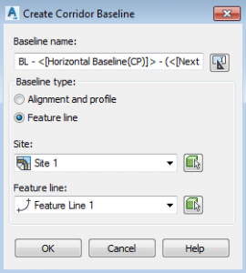
Feature lines can now be used as baselines for a Corridor in addition to Alignments. The elevations of the feature line are automatically used at the Vertical Baseline in the Corridor Properties > Parameters Tab.
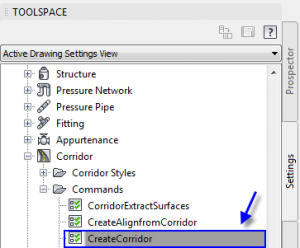
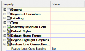
We can now choose whether to allow corridor feature lines can cross a baseline of the corridor. To check and adjust the feature before creating a corridor, open the settings for the Create Corridor Command.
4. External Style Management
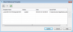
Civil 3D object Styles can now be standardized using reference templates. Previously, standards templates could be attached to drawings for controlling AutoCAD styles like text, dimensions and leaders as well as layers using the command Standards. Now, you can also attach style reference templates using the tool called Reference (AttachReferenceTemplate) found in the Manage Ribbon tab > Styles panel. When a drawing or template file is added as a Reference, the styles will be imported initially but are not automatically updated if the source file changes.
5. Roundabouts
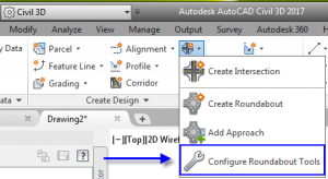
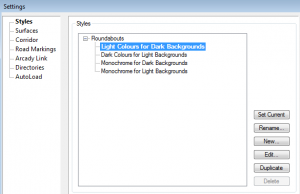
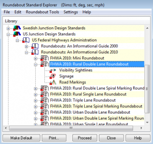
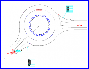
Roundabouts are now controlled with a new settings window that is similar to the Roundabout Settings in the Autodesk Vehicle Tracking Extension. The main advantages of the newly incorporated AVT settings is that different roundabout display styles are available as well as the AVT Design Standards library. These settings can be set prior to creating roundabouts and adjusted using Roundabout Properties.
Creating a Roundabout – Select a Design Standard
Contextual Ribbon for Roundabouts
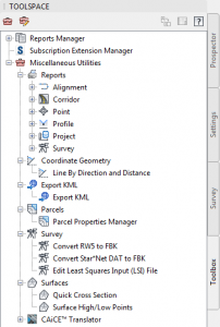
6. Miscellaneous Utilities (Toolbox)
The new sections in the toolbar are Reports, Coordinate Geometry, Export KML, Parcels, Survey, and Surfaces.
In Reports, txt files can be created from existing Alignments, Corridors, COGO Points, Profiles, Project Data and Survey Databases.
Under Coordinate Geometry, the line drawing tool Line by Direction and Distance can be found. This tool is similar to the Create Line by Bearing in the Home Ribbon Tab > Draw Panel.
The Export KML tool is used to export Civil 3D models and other 3D elements to .KML (Keyhole Markup Language) format.
In Parcels, the Parcel Properties Manager can be opened and used as an alternative option to Toolspace Details for editing Parcel objects and as well as to create tables in .CSV (Comma Separated Variable) format.
The Survey section contains tools for converting RW5 (TDS Raw Data) and Star*Net DAT files to FBK file format. An Edit Least Squares Input (LSI) File tool is also available at this location.
Under Surfaces, the Quick Cross Section tool is available for creating a temporary alignment, sample lines and section views. These are useful when reviewing a surface. Upon hitting Enter or Escape, the temporary objects disappear. The Surface High/Low Points tool is used to add new COGO points automatically at the highest and lowest elevations within a selected boundary of a surface.
For the new features in AutoCAD 2017, our free CAD Masters Update book is now available at books.cadmasters.com.
