Assign Elevations to Contours from an ESRI Shape File
Shape files (.shp) are a common file format in the GIS world, the file format is often used to exchange data between ESRI software and AutoCAD. Because each software package structures data differently, translating it into something useful can be challenging. For example, shape file vectors are always 2D. Though if they are contours, they should have an attribute that represents their elevation. In this post, I’ll go through importing an ESRI shape file containing contours, and moving those contours up to the appropriate elevation.
AutoCAD Map, Civil 3D, Land Desktop, and Topobase all have the ability to import a shape file. You’ll need the .shp, .shx, and .dbf files in order to import and perform the translation.
Part A – Import the Shape File:
- Start a new drawing.
- Type MAPIMPORT at the command line.
- Make sure Files of type is set to ESRI Shapefile, select the file, and click Open.
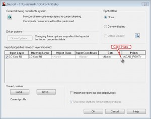
- In the Import dialog, select Import polygons as closed polylines.
- Click inside the cell under Data:
- Click Create object data.
- Click OK to close the Attribute Data dialog.
- Click OK to close the Import dialog.
When the file is done importing, zoom extents to see the results. Select a contour line and look at the Properties Palette. Notice that the AutoCAD Elevation property is 0, but that we also have an “OD” category in Properties. This is the object data that we brought in with file. Note which field contains your elevation data, then save and close the file.
Part B – Connect to the Imported DWG
- Start another new drawing.
- If the Map Task Pane is not currently showing, type MAPWSPACE at the command line and select On.
- In the Map Explorer tab, right-click Drawings and click Attach.
- Click the Create/Edit Aliases button,
, if the drawing is not on the C drive. Otherwise, skip to step 11.
- Enter a name for the Drive Alias. Note that it can be multiple characters, but no spaces are allowed.
- In the Drive Alias Administration dialog, click Browse.
- In the Choose Directory dialog, select the location where you saved the dwg in Part A.
- Click OK.
- In the Drive Alias Administration dialog, click Add.and then click Close.
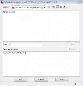
- In the Select drawings to attach dialog, for Look in, select the Alias that you just created.
- Select the drawing previously created in Part A, click Add.
- Click OK.
Part C – Query to Assign Elevations.
- In the Task Pane on the Map Explorer tab, expand Query Library, right-click Current Query and click Define.
- Click the Location button. Select All
- Click OK.
- For the Query Mode, select Draw.
- Click Alter Properties.
- Select Elevation and click Expression.
- In the Property Alteration Expression dialog, expand Object Data, expand the object data table and select the field that contains the elevation data
- Click OK.
- In the Set Property Alterations dialog, click Add
- Click OK.
- Click Execute Query.
Zoom extents, and there you have it, your contours in the drawing with the proper elevations assigned. Save the new drawing and then detatch the first drawing. (On the Map Explorer tab of the Task Pane right-click your drawing and click Detatch). You may discard it if you like. Be careful using this technique with live data as it is possible to modify the attached drawings. If you think that other GIS tools such as this would be helpful, consider Map 3D training to take full advantage of your software.


