Civil 3D Template Development Part 3 – Drawing Settings
Now that we have addressed the 1000-lb gorilla that is CAD Standards, we can finally get started on creating the templates. The very first item you should address are Drawing Settings. Open your template and on the Settings tab of the Civil 3D Toolspace. Right-click the template name and click Edit Drawing Settings.

Click the Ambient Settings tab to set units, precision, and format values for common civil engineering measurement properties. Some of the settings that I find myself changing are the following:
- The precision value for distance and elevation (2).
- The precision for both angle and direction (6).
- The format for both angle and direction (DDMMSS).
If most of your work is in a specific area, you can set the appropriate coordinate system in the Units and Zone tab (NAD83 CA, Zone III, US Foot in the lovely Bay Area). You can also set the default scale here.
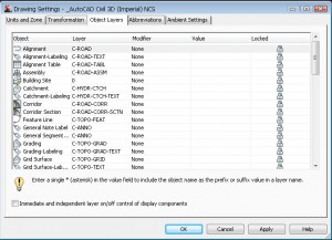
The Object Layers tab is where you will spending most of your time. Similar to how AutoCAD blocks have an insertion layer, Civil 3D objects have an insertion layer. This is where you define the insertion layer. You can also automatically add a prefix or suffix to the layer name (which I generally don’t do). To use the object name as the prefix or suffix, enter an asterisk (*) for value.
Working with the object layers can be tedious. First, you must make sure the AutoCAD layer exists. Then you must pick it in the Object Layers tab. There are between 50 and 60 object layers – hence the tedium.
I prefer to work in an Excel spreadsheet and copy the values from Excel to the template. The spreadsheet that I use is here. You can use the CMI Tools 2012 Import Object Layers command for this. To use the routine, first make sure that the Excel spreadsheet is open. Next, in Civil 3D, type, cmi_impol at the command line to run the command. Select Survey to load the survey layers or Civil to load the civil layers.
If you don’t like the fact that the layers also exist in AutoCAD, you can purge them. The object layer will then be created upon insertion of the object.
In the next part of this series, we’ll discuss Styles which many consider the “beef” of the template.

