AutoCAD 2012 – Edit the UCS Graphically
The UCS is a challenging aspect of AutoCAD, despite how innocent it seems. We often recommend that people never change the UCS. Here are a couple of reasons that we usually tell people always to leave the UCS set to the World Coordinate System (WCS).
- Changing the UCS makes coordinating drawing origins with other drawings and other consultants more difficult.
- Changing the UCS would break older commands, such as some of those found in Land Desktop.
However, if you are not concerned with either of these cases, there are times that it becomes very helpful to change the UCS. This will allow you to create mtext and linear dimensions on a drawing at an angle easily. It will also make it easier to use the ORTHO and POLAR drafting aids with a different axis. Finally, if you are modeling in 3D, changing the UCS becomes a necessity. AutoCAD 2012 has made it much easier to change the UCS since you can now modify it graphically.
In the previous versions of AutoCAD, users would have to be in the UCS command to make changes to the UCS. In the 2012 version of
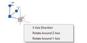
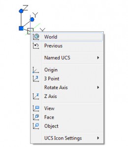
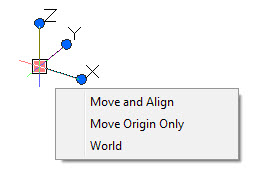
Hover over one of the axis grips and a menu will appear to allow you to move the axis or rotate around one of the other axes. Hover over the origin grip of the UCS and a menu will appear allowing you the following choices:
- Move and align the UCS origin with any object.
- Move the origin to specific point in your drawing.
- Restore the UCS back to the world coordinate system.
 Named UCS Example
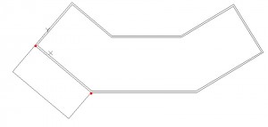
This example will focus on aligning the UCS relative to a non-orthogonal walls of a building. This is useful for using the ORTHO and POLAR drafting aids relative to the walls of the building. It is also useful to create mtext that is pre-aligned to the non-orthogonal walls.
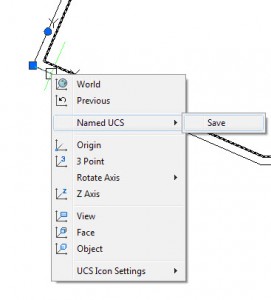
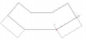
For this example, we’ll create two UCS settings, one for the left side called “SideL” and the right side called “SideR.”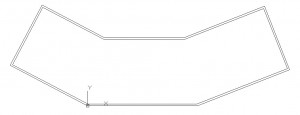
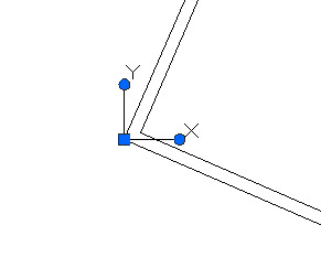
Click on the UCS icon and click on the square grip at the origin and snap to the bottom left corner of the building. Next, click on the circular grip and snap that on to the endpoint of that line, (endpoint represented with a red dot), to rotate the UCS. You have just created a user coordinate system. Note that since this UCS does not match the WCS, there is no square at the origin of the icon.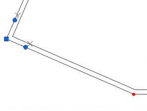
Repeat the pervious steps but with snap points on the other side of the building and name the UCS “SideR.” Now, when you right-click on the UCS icon you should be able to select either of your Named UCS settings to restore the UCS.
You are now able to use tools such as ORTHO and OTRACK with your relative UCS. Enjoy!

