
Mastering Corridor Targets in Autodesk Civil 3D
Designing Variable Lane Widths
If you’ve ever designed an urban streetscape or a residential subdivision, you know that the real world rarely plays nice with uniform offsets. Sidewalks need to widen around transit stops, pinch around utility poles, and flare into driveway aprons.
Trying to force these design realities using standard, static assemblies will leave you with a fragmented model and a lot of manual clean up. The secret to handling these shifting geometries efficiently lies in one of Civil 3D’s most powerful features: Corridor Targets.
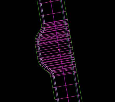
In this guide, we will look at how to leverage horizontal and vertical targets to master variable-width lanes.
Understanding the Power of Corridor Targets
By default, a subassembly (like a lane or sidewalk) has a fixed width and slope. Corridor Targets tell the subassembly to ignore its default values and dynamically stretch, shrink, or drop to match a specific AutoCAD or Civil 3D object.
To build variable widths, we primary use two types of targets:
- Width or Offset Targets (Horizontal): Forces the edge of your lane or sidewalk to follow a specific line in plan view.
- Slope or Elevation Targets (Vertical): Forces the subassembly to match a specific profile or 3D feature line elevation.
Step 1: Prepare Your Target Geometry
Before you even open the Corridor Properties, you need to define what your corridor is going to chase. You can use standard AutoCAD Polylines, but Civil 3D Feature Lines or Alignments are highly recommended for better data control.
For Lane Flares & Transitions
- Draw a continuous line representing the outside edge of the lane.
- Turn this geometry into a Feature Line, Alignment or Offset Alignment.
Offset Alignments
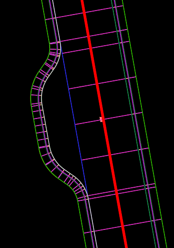
If you have varying lane widths, but the widths are relative to a road centerline, you may want to use an offset alignment at your edge of pavement. With this method, if your centerline geometry changes, your offset alignment will follow, while maintaining the specified offset distance. Here’s how to create an offset alignment:
- Navigate to the Home tab on the Ribbon.
- In the Create Design panel, click the drop-down arrow next to Alignment.
- Select Create Offset Alignment.
- Your command line will prompt you to select the centerline alignment.
- Click directly on the centerline alignment in your drawing, or press the Enter key to select the parent alignment name from a list dialog box.
Offset Alignment Widening (Optional)
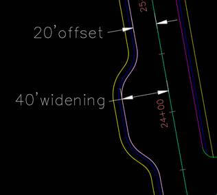
If the width of your lane varies, you probably need to add a widening to your offset alignment. Here’s how:
- In your drawing, click directly on the offset alignment.
- Once selected, the contextual Alignment tab will appear on the Ribbon.
- In the Modify panel, click the Add Widening button.
- Respond to the Command Line Prompts
(Note: Your offset alignment should start about 50 feet before and after the start and end of a widening.)
Civil 3D will guide you through the initial geometry configuration via the command line. Here is some guidance on the command line prompts:
- Since we don’t want to create a new alignment, type N (or press enter for No). Keeping it as “No” ensures the widening modifies the existing offset alignment dynamically rather than splitting it into a brand-new object.
- Type in the exact station where you want the widening’s entry taper to begin, or click a point visually along the alignment.
- Type or click the station where the widening’s exit taper should end.
- Enter the total target offset distance from the main centerline (e.g., if your base offset is 20 feet and you are adding a 20-foot lane, enter 40 feet.)
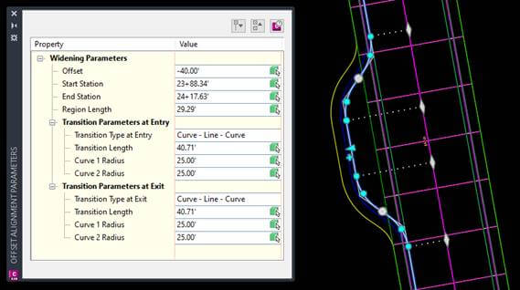
Immediately after specifying the offset, the Offset Alignment Parameters panorama/dialog box will expand. This grid gives you precise control over the three distinct regions of your widening:
- Widening Parameters: This is the full-width portion of your widening. You can adjust the exact start/end stations and modify the constant offset distance here.
- Transition Parameters at Entry: You can specify the taper by Length, a Taper Ratio (e.g., 1:10 or 10:1), or by explicitly setting the start and end stations of the transition.
- Transition Parameters at Exit: Controls the transition back down to the standard offset width. Like the entry taper, you can define this via length, ratio, or specific stationing.
- Note: By default, Civil 3D creates a linear taper. In the parameters grid, you can change the Taper Type from Linear to Curved-Tangent-Curve, Curve-Curve, or Tangent-Curve-Tangent if your design speed or local standards require smooth, curved transitions. (See Figure 3)
- Managing and Modifying the Widening
- Grip Editing: If you select the offset alignment, you will see blue geometric grips at the taper points and the widening edge. You can slide these grips along the alignment to visually adjust transition locations or widths.
- Adding Multiple Widenings: You can repeat this process to add multiple independent widenings (such as consecutive turn lanes) along the same offset alignment. They will all be managed within the same parameters grid.
Step 2: Set Up Your Assembly
To target successfully, your Assembly must use subassemblies that support targeting. Make sure the assembly lines are in the correct location that matches the Alignment or Feature line it will follow. (See Figure 4) The “Road-Right” assembly will follow the centerline alignment. While the “Road-Left” assembly will follow the offset alignment.

Step 3: Split Corridor into Regions
Think of a corridor region as a specific “zone” where a particular design rule applies. You rarely build a road or channel that looks exactly the same from start to finish. Splitting into regions is useful because it allows you to:
- Change Assemblies: Transition from a standard two-lane road to a road with a turn lane, a curb and gutter, or a bridge section.
- Manage Intersections & Driveways: You can drop curbs or widen the pavement at specific station ranges without affecting the rest of the alignment.
- Target Different Features: One region might need to daylight/grade to an existing surface, while another region next to a retaining wall might not need daylighting at all.
- Control Frequency: In sharp curves or complex areas, you might need a higher frequency of assembly insertions (e.g., every 5 feet) for accuracy. In straight sections, you can loosen the frequency (e.g., every 50 feet) to keep your drawing file size small and fast.
How to Split a Corridor into Regions
- Select the corridor in model space.
- Look up at the contextual Corridor tab that appears on the Ribbon.
- In the Modify Region panel, click the Split Region button.
- Hover over your corridor. Civil 3D will highlight the regions. Click inside the region you want to split.
- The command line will ask you to select a station. You can either:
- Click a point on the screen (use snaps for precision, like a station label line).
- Type the exact station number into the command line and hit Enter.
- If you have more splits to make, keep clicking stations. When you are done, press Enter or Esc to finish.
Step 4: Adding Baselines
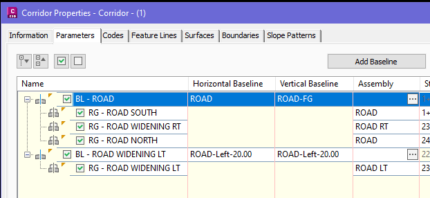
If you have a corridor with curb subassemblies, the curb cannot use targets. To get the curb looking correct, you may need to add an additional baseline. Adding a baseline is easy using these steps:
- Click on the corridor in your drawing area, right-click, and select Corridor Properties.
- In the Corridor Properties dialog box, click on the Parameters tab.
- Click the Add Baseline button (located on the top-right of the dialog box).
- The horizontal geometry of your baseline will either come from an alignment or feature line.
- Alignment and Profile: Select your horizontal alignment and its corresponding design profile.
- Feature Line: Select a 3D feature line or site/survey figure directly from the drawing or a list.
- Click apply and choose rebuild the corridor when prompted. Click OK to close.
Step 5: Assigning the Targets in the Corridor
Once your geometry and assemblies are prepped, it’s time to hook them up.
- Go to Corridor Properties > Parameters Tab > Set All Targets (or click the Target ellipsis next to your Region)
- On the Offset and Elevation tab look for the following:
| Subassembly Component | Target Type | Object to Select |
| Lane – Width Target | Offset Target | Select the Feature Line/Alignment representing the variable outside edge. |
| Lane – Outside Elevation Target | Elevation Target | (optional) Select a Profile or Feature Line if the lane cross-slope must change. |
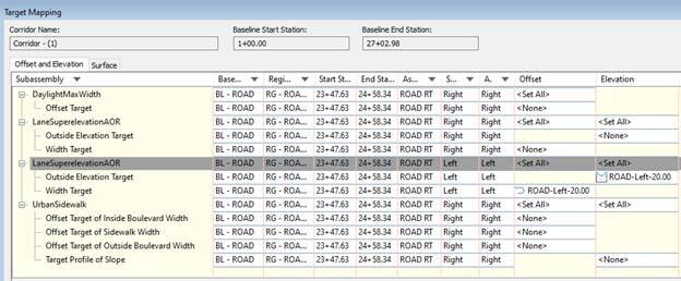
- After selecting target objects, select “rebuild corridor” and click OK.
Step 6: Adding Frequency Lines
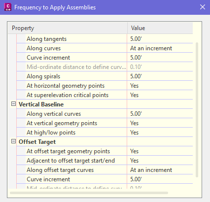
- When an assembly wraps around a curve, it doesn’t come out very smooth due to the triangulation between subassembly points. However, if you add more frequency lines that are closer together, you can get a better-looking corridor. Follow these steps:
- Select your corridor in model space.
- In the contextual ribbon > Modify Region panel > click Edit Frequency.
- In model space, select the corridor region you would like to edit.
- In the “Frequency to Apply Assemblies” dialog box, change the frequency values to something smaller. (Tip: I like to use 5’ apart.)
- Click OK.
Wrapping Up
Mastering corridor targets elevates your Civil 3D skills from basic drafting to advanced BIM modeling. By letting Feature Lines control your lane widths and elevations, you ensure that any future design changes only require moving a feature line and hitting Rebuild.
