AutoCAD Parametric Constraints
Of all the new features added to AutoCAD in the last few release cycles, one of the most underused has been Parametric Constraints. What is a parametric constraint? It’s a constraint that can be numerically or geometrically driven. For example, you can specify that a line is precisely parallel and 10 feet offset from an adjacent line. Modifying the controlling line updates the constrained line. With the use of numerical parameters, you can change your drawing by adjusting values instead of working directly with linework. This is where the idea of parameter driven programs such as Revit comes from. They take this concept and apply it to a specific discipline and do it very well. This post will discuss the concept in AutoCAD, and helps you see how parameter driven programs can benefit you.
When first implementing parametric constraints in AutoCAD, it is easy to end up with over constrained geometry that is frustrating to work with. However, if you keep your constraints well grouped for a specific purpose, they can make it much easier to make design changes during the life of a project.
For example, if you need to draw a structural beam plan, but have not yet determined the final sizes, you can still get the majority of the drafting done initially. Then once the sizes are determined, you can update the parameters to reflect the final values.
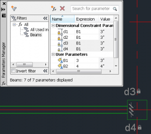
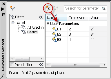
In AutoCAD, the first step to getting a drawing setup is to define your parameters. Open up the Parameters Manager using the PARAMETERS command. Create User Parameters for the sizes that you’ll need. In this case, we are referencing the center line, so we want to use half of our beam dimension. Later on, if we change the values of these parameters, we’ll find that the linework in the drawing will update.
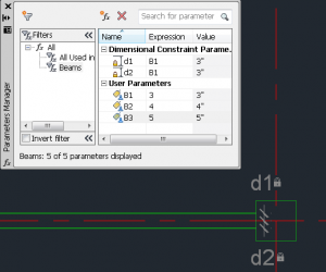
Once the parameters for the beams are defined, they can then be applied to linework in the drawing. In this case, we want the linear constraint, DCLINEAR. Note that the linear constraint is going to want to operate from the end point of the lines, so you will need a beam centerline drawn with the same length of the beam itself. Finally, lock the centerline into place using the GCFIX constraint to prevent the beam from moving.
Now that the constraints are created, you can change the expression of the constraint to match the User Parameter value that you want. If you copy the beam linework as well as the constraints, new constraints are created that reference the same User Parameter. Note that you will have to fix the centerline after copying. If you will be doing this frequently, you might want to take advantage of the Action Recorder.

Even though it’s more work to setup initially, parameteric driven tools can make using AutoCAD easier. Likewise, the same is true for BIM programs such as Revit. There is more setup involved, but they can drastically speed up productivity once you get going.


