Coordinate Transformations – Part 3 – FDO
Now that we’ve seen how to translate point files and drawings from one coordinate system to another, let’s take a look at another option, translating data sources. Feature Data Objects (FDO) are data sources that can be connected to a drawing using AutoCAD Map 3D or Civil 3D. We can connect to a variety of data sources including Autodesk SDF’s, ESRI shape files, ArcSDE databases, raster images, and the like. The variety of data types that we can connect to makes it a very power tool. Not to mention, the ability to theme objects based on the associated data and on-the-fly coordinate transformations.
First, assign a coordinate system to the current drawing:
- Type MAPWSPACE at the command line, press Enter, and select On.
- In the Map Explorer tab of the Task Pane, right-click on Current Drawing and click Coordinate System.
- Click the Select Coordinate System button.
- Select the appropriate category and coordinate system in that category (the coordinate system in which the drawing currently resides).
- Click OK to close the Select Global Coordinate System window.
- Click OK to close the Assign Global Coordinate System window.
Next, connect to the data source:
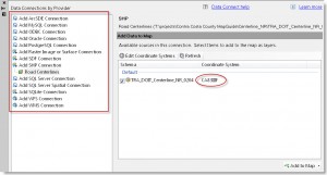
- In the Task Pane, click the Data, and click Connect to Data…
- Choose the appropriate Data Connection Provider on the left.
- Give the connection a name, specify the source file or folder, and click Connect.
If the data source contains metadata assigning the coordinate system, the coordinate system will be displayed in the Coordinate System column. If that’s the case, the transformation will occur automatically, simply click the Add to Map button and you’re done. If the row says <unknown>, click the Edit Coordinate Systems button, click Edit, and set the coordinate system of the source file before you click Add to Map.

