Subassembly Composer – Part 2
In Part 1, I shared my initial thoughts on the Subassembly Composer. I’ve had more time to look at the subassembly composer and have documented some questions, answers, and notes from the experience.
How do I have input (variable) parameters?
In the bottom right corner of the Subassembly Composer, there is a tab for Input Parameters. Make sure that the names for the points match the input parameters. This is very straight-forward. The most difficult part will be keeping the names well organized and logical.

In the bottom right corner of the Subassembly Composer, there is a tab for Target Parameters. These are set-up much like the input parameters. Select the name from the combo boxes in the properties of a point feature.

The side parameter should work in the default settings. However, if you have target profiles defined, then you will not see the changes in the preview. It will work fine in Civil 3D though and you will see the side change inside of Civil 3D when you change properties of the subassembly from Left to Right.
How do I make it easier to work with all these geometry features?
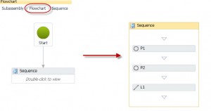
You’ll quickly find that working with a lot boxes and arrows is tedious. Using Sequences will make it much easier to manipulate the geometry features. Drag and drop a Sequence from the tools into the flowchart. Double-click on the sequence to open it up and insert geometry features into it. If you want to add items to the sequence that already exist in the flow chart, you can cut, copy and paste elements one at a time into the sequence. The main advantage of the sequence is that it lets you change the order of the components easier. Note that you might have to return to the flowchart to access property changes from other elements in the sequence. To return to the default view, click Flowchart in the upper left corner. Then when you double-click to return to the sequence, everything should be updated.

How do I define shapes in my subassembly?
The main limitation that jumped out at me initially is that you cannot define a shape in the subassembly. Note that someone on the forum has put in a request for this and Peter Funk from Autodesk has acknowledged that this should be a pretty key feature.
What are some Best Practices?
When this tool is officially released, it’s going to be a powerful tool, there’s no doubt about that. It also has the potential to be a humongous time suck. Here are some suggested best practices for all of us when we get the release version:
- Check to make sure that the stock subassemblies will not suffice before creating one from scratch.
- Define a single purpose for your subassembly before you start.
- Keep your custom subassemblies as small and simple as possible.
- Determine a naming system for all of your parameters.
- Test frequently as you build. You might need to delete the definition of the subassembly and then re-import the pkt file incase Civil 3D is not updating with your changes.:
- XP – C:\Documents and Settings\All Users\Application Data\Autodesk\C3D 2011\enu\Imported Tools
- Vista/W7 – C:\ProgramData\Autodesk\C3D 2011\enu\Imported Tools


