Revit Electrical-Lighting Plan
Personally, I find some aspects of Revit very intuitive and easy to learn, such as placing walls, windows, and doors. Revit becomes more difficult when there are many different ways to achieve the same goal. Both cases come into play when creating an Electrical-Lighting plan in Revit, some parts are very straightforward, while others, like setting up views are not. This post will present one method to show both electrical and lighting elements on a sheet.
Electric – Create Switches and Outlets
To create the switches and outlets, you will use the Place Component command. It maybe be obvious, but you need walls as a host object before you can place switches and outlets. If you need more families for types of switches and outlets, you can find them in the default libraries.
Lighting – Create Ceiling and Lights
The first step to creating lights is to create a ceiling. Make sure that you are working in one of the Ceiling Plans. The ceiling is the host object for any lights that you want to place. As long as you have a ceiling, just like the switches and outlets, you can use the Place Component command to insert lights. Note that there are many options for the types of lights available. The type of light becomes more critical if you are planning to create rendered views of your structure.
View – Duplicate a View, Visibility Graphics, View Range
Setting up the view is the most difficult part of creating an electrical plan. Before you start to modify any view settings, you are going to want to create a copy of your normal floor plan view. In the Project Browser, under Floor Plans, right click your view, point to Duplicate View and click Duplicate. In the new view, in the Properties panel, next to Visilbility/Graphics, click Edit. Make sure that Electrical Equipment and Lighting Fixtures are selected. Turn off all the other categories that you do not want to see. You will also want to set the Discipline to Electrical in the View Properties.
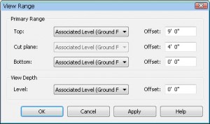
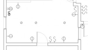
Next we need to set the view range. In the Properties panel, next to View Range, click Edit. Just to test to make sure that it’s possible to see all of your electrical equipment and lighting fixtures, set the Bottom to the level that you are working on and set the Top to Unlimited. You should be able to see switches, outlets, and lights with this setting. If you’re working on a single story building, then this will suffice, otherwise you’ll need to set the top appropriately so that the view range is large enough to encompass the lights that are in the ceiling.
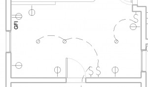
The last step, is to drag and drop the view that you created onto a new sheet. If you have Revit MEP, then you can model the wiring. However, I’m going to assume that you are using Revit Architecture, so we will represent the wiring as 2D linework. First, set the scale for the view. Then, you can create the lines for the schematic on top of the view in the sheet by using the Detail Line command and creating arcs. Of course, these are not modeled, but this should be sufficient for a residential remodel.


