Civil 3D Pipe Styles
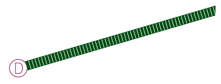
If you are using Civil 3D, you may find that working with styles can be tricky. In this blog, I will show you how to create a dashed pipe style, like the one shown below, and then how to set it as the default style for your pipes.

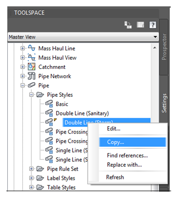
Create Pipe Style
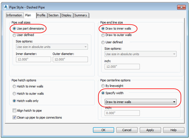
On the Information Tab of the Pipe Style window, you can rename the style. I called mine “Dashed Pipe”. On the Plan Tab, Choose “use part dimensions” for the Pipe wall sizes. Then choose “draw to inner walls” for the Pipe end line size. Lastly, for the Pipe centerline options, choose “Specify width” and from the drop down menu, choose “Draw to inner walls”. It is important that your selection for “pipe end line size” matches your selection for the centerline width.
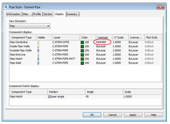
On the Display Tab, make sure your View Direction is set to “plan”. Check that your Pipe Centerline, Inside Pipe Walls and Pipe End Line are set to be Visible. Also set the Linetype for your centerline to be DASHED or make sure that the centerline layer is already set to DASHED . Click OK.
Set Created Pipe Style as Default
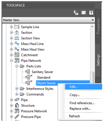
Now that the pipe style has been created, we need to set it as our default pipe style. To do this, go to the Settings Tab of Toolspace. First expand the Pipe Network category. Then expand the Parts Lists category. Right Click on a parts list and click Edit.
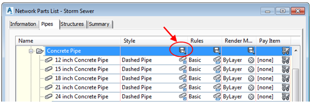
On the Pipes Tab of the Network Parts List window, expand a Part Family to show all the Part Sizes. In the Style column, you can see the default styles being used. If you would
like to change all of the styles at once, you can click to apply to all part sizes in the family.
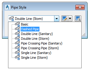
Lastly, you can choose your style from the Pipe Style menu.
Now, when you create a new pipe, the “Dashed Pipe” style should be your default style. You can also change the style of any pipes you have already drawn by selecting the pipe and going to Pipe Properties in the Ribbon. If your pipe style doesn’t look right (i.e. the dashes are too close together or too far apart, as shown below) it might be due to your linetype scale.
We recommend that you set the following system variables to a value of 1.
LTSCALE (linetype scale)
MSLTSCALE (model space linetype scale)
PSLTSCALE (paper space linetype scale)
Setting MSLTSCALE and PSLTSCALE to a value of 1 makes all linetypes annotative. Meaning, the length of the dash will change in proportion to the annotation scale of your drawing.

