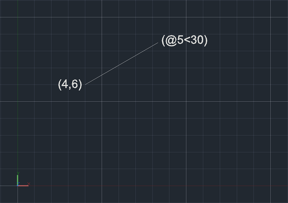
COORDINATE SYSTEMS IN AUTOCAD
Using coordinates to specify locations can be a challenge in AutoCAD. It helps to take our time to understand the underlying concepts.
CARTESIAN COORDINATE SYSTEM
The word “Cartesian” comes from the philosopher Descartes, who came up with the idea. One day Descartes was staring at a fly on the floor. It occurred to him that he could describe the fly’s location floor by noting its distance from two of the walls.
In this example, the floor is a coordinate plane.
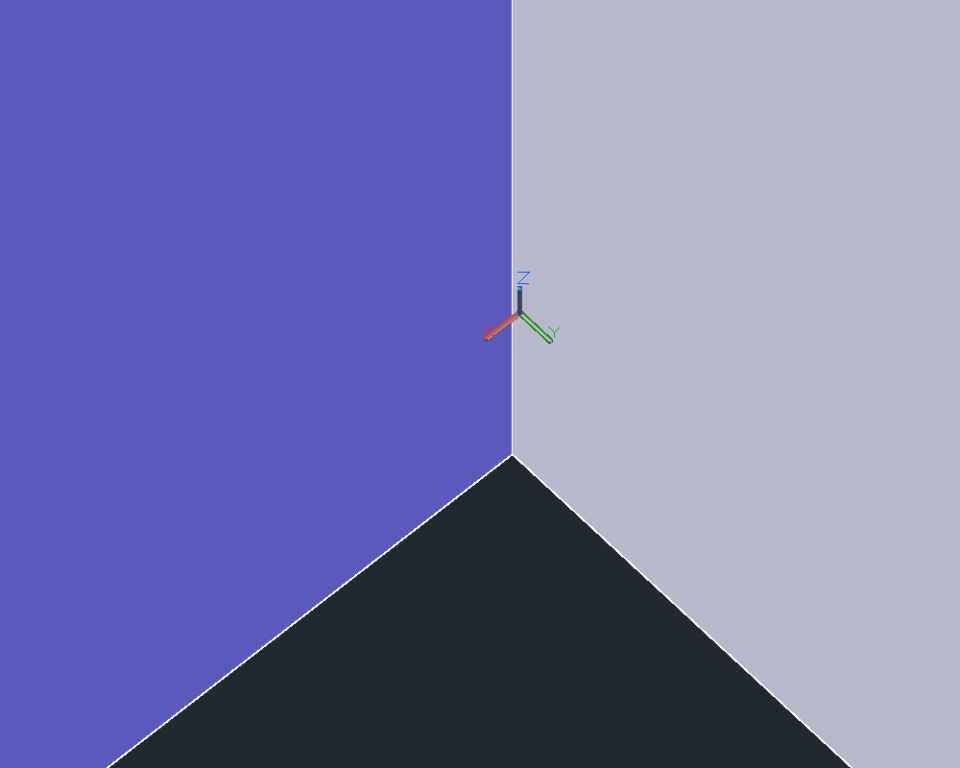
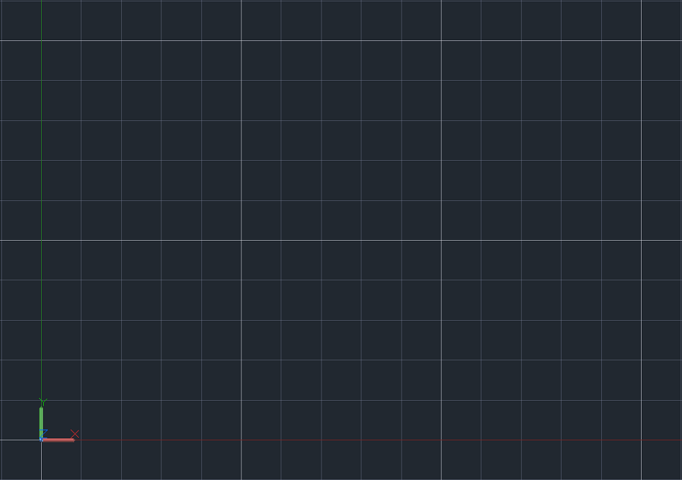
Note the UCS icon. It is composed of stubs sticking out in the x-direction, the y-direction, and, the z-direction. The z-direction is hidden if you are working in 2D, but you can think of it as coming out of the page (or monitor, I suppose). The place where the stubs intersect is called the origin.
If you imagine the x-stub extending out indefinitely, this is the x-axis. If you imagine the y-stub extending out indefinitely, this is the y-axis. Any point along the floor can be given as (x, y), where x is a distance along the x-axis, and y is a distance along the y-axis.
- Conventionally, the x-axis is horizontal, with positive number signifying a move to the right, and a negative number signifying a move to the left.
- Conventionally, the y-axis is vertical, with positive numbers signifying a move up, and negative numbers signifying a move down.
In the status bar at the bottom of AutoCAD, there is a grid that can be turned on or off. Some people like the grid on in order to facilitate counting along the x and y axis. The F7 key is a quick way to toggle the grid on and off. There is also a grid snap tool (F9), which allows snapping to the grid. Right click on the grid or grid snap tools to change their settings. Another tool that can be used is ORTHO mode (F8), which constrains cursor movement to the horizontal and vertical directions.
Coordinates, like object snaps, are a way of introducing more precision to our work.
Coordinates act as subcommands in AutoCAD (meaning you need another command active for them to be meaningful). As an example, you could start a command, such as line, and then practice typing in coordinates and pressing [enter] to place a vertex. This exercise is fleshed out in the section below.
ABSOLUTE COORDINATE ENTRY
Absolute coordinate entry is the default. Absolute coordinate entry always counts from the origin. When drawing lines, AutoCAD is ready to place the next vertex wherever you tell it to go:
- Type L on the command line and press enter
- Type 4,6 on the command line and press enter
- Type 5,3 on the command line and press enter
- Press enter to finish the Line command
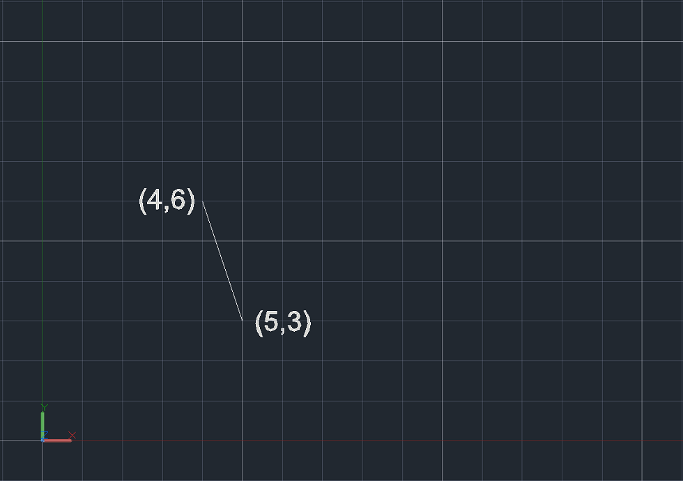
We just told AutoCAD we wanted a line starting at 4,6, and ending at 5,3. It made a segment between those two points. The first point is 4 to the right and 6 up from the origin. The second point is 5 to the right and 3 up from the origin. The line is the shortest distance between those two points.
RELATIVE COORDINATE ENTRY
For relative coordinates, AutoCAD does not count from 0,0. Instead, the reference point is the previous point in the drawing. Let’s draw another line, and see what it looks like compared to the old one:
- Type L on the command line and press enter
- Type 4,6 on the command line and press enter
- Type @5,3 on the command line and press enter
- Press enter to finish the line command
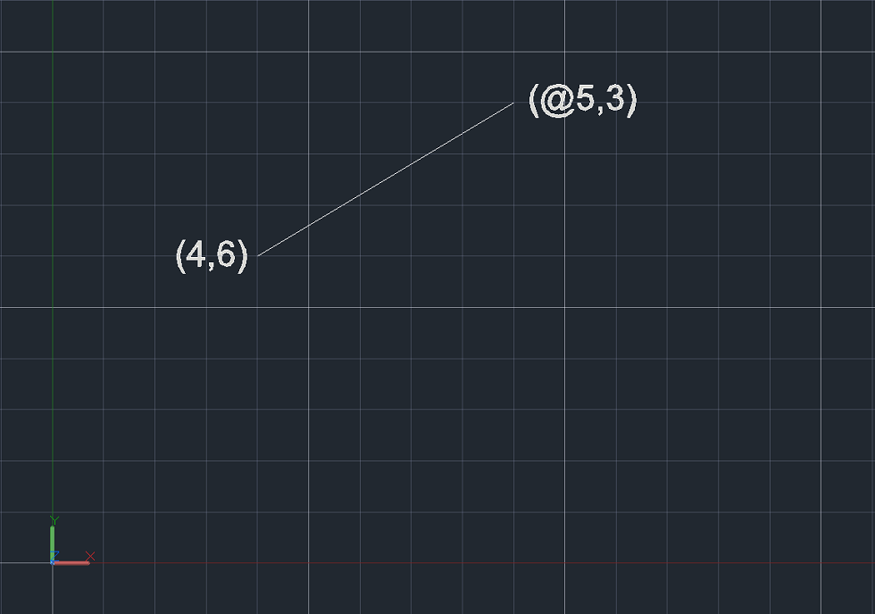
AutoCAD recognizes the @ symbol as instructions to count using relative coordinates.
Notice the difference. While both lines made thus far started at the same point, this time, for the second vertex, AutoCAD counted 5 over and 3 up from the first vertex, and made the line between those two locales.
POLAR COORDINATE SYSTEM
Polar coordinates are named for their “pole”; the reference point to start counting from, which is similar in concept to the origin. Polar coordinates employ one radial distance and one angle (by convention, the angle is measured counterclockwise from the x-axis). The angle signifies the direction, and the distance is how far to go in that direction from the pole.
Polar coordinates in AutoCAD are given as R<Degrees, where:
- “R” is the radial distance
- “<” is the less than sign (but in this case represents the angle)
- “Degrees” is the value of the angle in degrees
Like Cartesian coordinates, polar coordinates are employed as a subcommand.
The analogue to ORTHO mode is POLAR tracking (F10). Polar tracking restricts cursor movement to specified angles. The user can specify the acceptable angle increments by right-clicking the icon
Relative coordinates also work with polar input.
Let’s delete the lines we drew and work via the command line again:
- Type L on the command line and press enter
- Type 4,6 on the command line and press enter
- Type @5<60 on the command line and press enter
- Press enter to finish the line command
The above line started at 4,6 (which is input in absolute Cartesian coordinates). Since the next line had the @ symbol, that means the previous point (4,6), became the pole, or reference point for the relative coordinates.
We input the polar coordinates as @5<60, which means the length of the line is 5 and the angle counterclockwise from the x-axis is 60 degrees.
WRAP UP
AutoCAD, for the most part, is going to do what you tell it to do. Improving at AutoCAD is all about puzzling out how to give the program directions from A to B, and being precise in your drawings.
What’s that lovely expression?
It’s all relative, you see.


